Headset Tracking for VR/AR
Summary
I had been looking into the Oculus Rift + Touch for awhile, but I knew next-to-nothing about the math behind its tracking algorithms. A few months back, I read a Medium article where some guys had built their own inexpensive open-source virtual reality headset. I found the project on Github, looked through their implementation and saw that there wasn’t much in the way of headset tracking, yet. I saw that they used an IMU - inertial measurement unit - for estimating rotations from raw measurements. From my experience with tracking systems, this seemed a suboptimal approach because of sensor noise, bias, etc… so I decided to dig-in deep and add inertial tracking. Doing this, I believed, would improve the VR experience by avoiding spurious orientation estimates due to IMU issues. In this post, I will talk about my experience researching and implementing a tracking filter in the project. See here for the algorithm implementation.
The Approach, with all of the Gory Math
The approach I’m going to discuss can be found here. As a prereq, you should have a background in the mathematics of quaternions, because the approach I took utilizes them heavily. Briefly, a quaternion can be thought of as an object that parametrizes a rotation. Firstly, there is an axis of rotation, which is a unit vector \(\hat{\mathbf{v}}\) that a point, or set of points, is rotated about. The second parameter of a quaternion is the angle of rotation, a scalar \(\theta\). Putting these two things together, we have a quaternion \(\tilde{q}(\mathbf{v}, \theta)\) that describes a rotation about \(\hat{\mathbf{v}}\) with magnitude \(0 \le \theta \le 2 \pi\). Quaternions are conceptually similar to Euler rotation matrices, however quaternions are preferred because of some undesirable properties of rotation matrices.
My first step when trying to improve upon existing projects is usually to understand what data is available already. The project already included an IMU, either the 6-axis MPU-6050 or the 9-axis MPU-9150, which output an acceleration vector - 3 axes, an angular velocity vector - 3 more axes, and, for the MPU-9150, a magnetic direction vector - 3 more axes. I will discuss the contribution of all of these measurement quantities in course, but I will begin with the angular velocity vector, \(\mathbf{\omega}\).
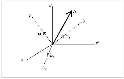
See above for a picture representing global and local, or body, coordinate systems. The global frame has coordinates with “primes”, e.g. \(x'\). Important: The above image is stock; for the discussions below, replace \(z\) in the above image with \(y\), \(x\) with \(z\), and \(y\) with \(x\).
A note on notation: I use \(\hat{-}\)’s for unit vectors and \(\tilde{-}\)’s for estimated quantities.
The angular velocity vector, \(\mathbf{\omega}\), is a measurement of angular rotation rates about a set of principle axes, aka a body coordinate system. \(\mathbf{\omega} \equiv [\omega_x, \omega_y, \omega_z]^T\). As with most sensors, the output needs to be calibrated to account for temperature effects, bias, scaling, etc… The calibrated measurement, \(\tilde{\mathbf{\omega}}\), can be written as
\[\tilde{\mathbf{\omega}} = A \mathbf{\omega} + \mathbf{b}\]\(A\) is a \(3 \times 3\)-matrix and \(\mathbf{b}\) is a \(3 \times 1\) bias vector. The coefficients of \(A\) and \(\mathbf{b}\) are determined during a calibration procedure. The normalized vector
\[\hat{\mathbf{v}} = \frac{\tilde{\mathbf{\omega}}}{||\tilde{\mathbf{\omega}}||}\]forms the axis of rotation of a quaternion, and the amount of angle change over the current timestep, \(\Delta t\), \(\Delta \tilde{\theta}_k = ||\tilde{\mathbf{\omega}}|| \Delta t\), is the magnitude of rotation of the same quaternion.
This quaternion, \(\Delta \tilde{q}_k \equiv q(\hat{\mathbf{v}}, \Delta \tilde{\theta}_k)\), represents an incremental change in estimated orientation from a previous state described by the quaternion \(\tilde{q}_{k-1}\). The orientation at the current timestep, \(k \Delta t\), can be updated recursively
\[\tilde{q}_k = \Delta \tilde{q}_k * \tilde{q}_{k-1}\]where * is the quaternion product and, yes, order does matter. This is because quaternion algebra, like matrix algebra, is non-Abelian.
Ok, so we have a quaternion that represents the estimated headset’s orientation at some timestep, \(k \Delta t\) based on the calibrated angular velocity reading. It turns out that these estimates can become unreliable over time due to a phenomena known as IMU drift. This drift error in our estimate can be decomposed as tilt and yaw errors. The tilt error, denoted \(d_{tilt}\), is the magnitude of difference between the estimated quaternion and truth in the pitch and roll channels, whereas yaw error, \(d_{yaw}\), comes from the remaining yaw channel. Since these channels represent rotations about orthogonal axes, the total error, \(d\), can be written as the product of quaternions, \(d = d_{tilt} * d_{yaw}\). Somewhat confusingly, order does not matter here, because whether you apply the yaw or tilt correction first, the end result will be the same.
I have only considered the true drift error in the previous paragraph. In practice, however, one can usually only compute an estimate of the drift errors discussed. I will now go through how to compute these estimates.
\(\tilde{d}_{tilt}\)
 Copyright 2015,2016 Steven M. LaValle
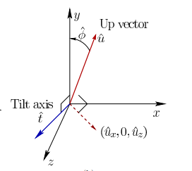
Tilt error is due to the estimated “up” vector, \(\tilde{\mathbf{u}} = [\tilde{u}_x, \tilde{u}_y, \tilde{u}_z]\), being out-of-alignment with the actual “up” vector, the \(+y\)-axis. If the IMU is only rotating, not translating, this is an ok approach, but it will break down if the IMU is accelerating. This approach hinges on the fact that the measured IMU acceleration needs to be very nearly the 9.8 meters-per-second-squared of gravitational acceleration. For a VR headset, if the wearer is seated in a chair, this seems a decent assumption. The vector \(\tilde{\mathbf{u}}\) is computed by rotating the calibrated acceleration measurement vector \(\tilde{\mathbf{a}}\) into global coordinates:
\[\tilde{\mathbf{u}} = \tilde{q}_k * \tilde{\mathbf{a}} * \tilde{q}_k^{-1}\]Now, the angular difference between the global \(y\)-axis and \(\tilde{\mathbf{u}}\) can be computed with the law-of-cosines:
\[\tilde \phi = \cos^{-1} \bigl ( \frac{\tilde{\mathbf{u}} \cdot \hat{\mathbf{y}}}{||\tilde{\mathbf{u}}||} \bigr ),\]with \(\hat{\mathbf{y}} = [0, 1, 0]^T\). We have the rotation angle for our quaternion, now we need the axis. The tilt-axis, \(\tilde{\mathbf{t}}\) is the vector we need to rotate about to bring \(\tilde{\mathbf{u}}\) and \(\hat{\mathbf{y}}\) into alignment. Such an axis would need to be orthogonal to both \(\tilde{\mathbf{u}}\) and \(\hat{\mathbf{y}}\). There are two choices based upon directionality, the one associated with the positive rotation -from \(\tilde{\mathbf{u}}\) towards \(\hat{\mathbf{y}}\)- is:
\[\tilde{\mathbf{t}} = \begin{bmatrix} \tilde{u}_z \\ 0 \\ -\tilde{u}_x \\ \end{bmatrix}\]The tilt error can now be written as a quaternion:
\[\tilde{d}_{tilt} = q \bigl ( \frac{\tilde{\mathbf{t}}}{||\tilde{\mathbf{t}}||}, \hat \phi \bigr )\]\(\tilde{d}_{yaw}\), but only if you have the MPU-9150, or equivalent
Tilt error only estimates drift in pitch and roll, but what about yaw? A priori knowledge about gravity won’t help here, so the measured acceleration won’t be of any use. If we were able to have some way of recognizing a landmark in the \(xz\)-plane with the IMU, then we could compare our estimate of that landmark’s position to our a priori estimate. The magnetic north-pole is such a landmark, and if we have the MPU-9150, or equivalent, we have a magnetic compass that will generate a calibrated measurement, \(\tilde{\mathbf{m}}\), that we can rotate and compare to true north. We can define our global coordinate system such that the \(z\)-axis is aligned opposite to true north. Our estimate of true north, \(\tilde{\mathbf{n}}\) then follows much the same as the tilt error calculations:
\[\tilde{\mathbf{n}} = \tilde{q}_k * \tilde{\mathbf{m}} * \tilde{q}_k^{-1},\]from which we compute an angular offset:
\[\hat \psi = \cos^{-1} \bigl ( \frac{-\tilde{\mathbf{n}} \cdot \hat{\mathbf{z}}}{||\tilde{\mathbf{n}}||} \bigr ).\]The axis of rotation is just \(\hat{\mathbf{y}}\), the yaw axis, from which the estimated yaw drift is computed:
\[\tilde{d}_{yaw} = q \bigl ( \hat{\mathbf{y}}, \hat \psi \bigr )\]If the magnetic compass reading is not available, \(\tilde{d}_{yaw}\) is set to the identity quaternion.
Putting it all Together
The estimated error quaternion, \(\tilde{d}\), can be deconstructed into a rotation axis and an angle. Let’s call the angle $\theta$ and the axis \(\hat{\mathbf{v}}\). Using these quantities, we can construct a complementary estimate
\[\tilde{q}_k' = q(\hat{\mathbf{v}}, -\alpha \theta) * \tilde{q}_k\]with \(\alpha\) as a weighting factor with \(0 \le \alpha \le 1\). Increasing \(\alpha\) will more heavily compensate for drift in your estimate.
The parameter \(\alpha\) should be selected heuristically; literally, an “eyeball-test”. ![]()
The Implementation
You can check out the actual implementation here.
I would like to point out just a few things about the i2cdev library:
- It has a pretty nice API. The
get*’s andset*’s are well named and use camel-case consistently. Additionally, A lot of methods for accessing raw measurements and computing intermediate estimates from them are exposed. For example, the gravity estimate associated with the current orientation quaternion can be polled directly withdmpGetGravity(&,&), which returns the estimated “up” vector. - Quaternions and vectors are supported out-of-the-box, with methods to do useful things like normalization, compute products, etc…
- For the most part, everything is very simple and intuitive.
All necessary math operations were provided by either i2cdev or Arduino; no custom functions were written. This was really nice because I feel it made the implementation cleaner and easier to work through.
Parting Thoughts
If you have made it this far, then congratulations are in order! The details in this post can be very difficult to get through without a significant background in rotational math; specifically quaternions and vectors. I have tried to pare down the explanation to only the bits that I found essential. I have also tried, whenever possible, to include pictures so that you, the reader, could visualize what was going on.
I wanted to write this post in an ongoing effort to engage my mind in thinking on how to explain what I work on so that most others can understand. In that sense it is mostly for me, but in another sense I really do want to ensure that someone reading this would find something that they could recall and refer back to when working on similar problems. If you feel something could be clearer, please let me know. Thanks for reading!