Building the F1TENTH Racecar
I feel like I have been putting together my Traxxas RC car forever. When I started back in 2017, the F1TENTH project wasn’t even a thing yet. Luckily for me, the documentation in this project is pretty easy to follow. I highlight some notable exceptions below.
Bill-of-Materials (BoM)
For the most part, the Master BoM is pretty good. There were two areas that required additional research on my part though:
- Which material to choose for the laser-cut platform deck?
- Which materials to choose for the power distribution module (PDM)?
For the first item, it took some iteration. I started by ordering two black matte acrylic platform decks from Ponoko but I snapped both of them when assembling the car. For the next order, I tried two stronger (and more expensive) materials - Black Melamine and Black Delrin. I installed the Black Delrin deck and it worked out fine.
The second item required me to do some digging in the f1tenth forums. Thankfully, I was able to find an updated BoM there.
Though it is not called out directly in the BoM, a valuable piece of test equipment to have is a digital power supply like this one. Although it can’t be used to power the VESC when it is driving the motors (more on this in the VESC section below), it can be used while setting up the rest of the physical setup, including the Jetson computer.
The primary reason it took me so long to put this kit together is the all-in price tag: about $3k. This is pretty steep for a hobbyist like me, but I finally was able to pull everything together earlier this year.
Traxxas modifications
The steps here were performed with no modifications required. As I mentioned previously, I had some issues with the platform deck material having insufficient integrity to be properly installed.
I added the foam front fender from the RACECAR/J kit to lessen the impact of any collisions.
Building the Power Distribution Module (PDM)
The PDM takes in a variable voltage and outputs regulated voltage on 12 and 8V output buses. The 12V output is primarily to power the Jetson NX companion computer. The 8V output is for powering the Hokuyo lidar sensor.
I am not an electrical engineer nor am I an electronics technician. It has been several years since I have had to solder anything, so I had to proceed more carefully through this step.
Soldering the PDM
The first consideration in soldering was ordering the printed circuit board (PCB) to add the electronic components to. The vendor (Oshpark) requires a minimum of three PCBs per order for fabrication, so I decided to build three full PDM assemblies. This would provide adequate backup should I blow up any of them along the way.
I remembered from my introductory electronics lab in college that certain electronic components, like diodes, have polarity; that is, there are preferred mounting orientations of components relative to current flow through a circuit. I did not recall that capacitors had polarity, so it was a good thing I found this diagram:
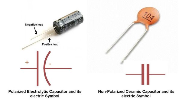
Some capacitors do have polarity - there is an anode (+) and a cathode (-) and you need to make sure to install these components correctly. Polarized capacitors are noted in schematics differently than non-polarized ones; see picture above.
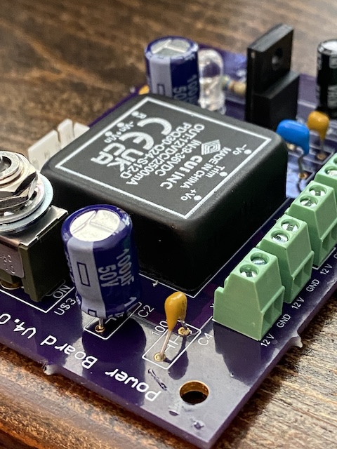
Specific to the printed PDM PCB: the anode has a longer lead than the cathode and should be installed in the hole nearest the printed component id. Below is a picture of the assembled PDM showing the correct orientations of the polarized electrolytic capacitors.
The only word of advice I can give would-be builders here is this: get a really fine tip for your soldering iron. Some of the work is rather delicate. You will want some means (like this) of keeping the board fixed without having to hold it with a free hand.
Testing
Testing is actually pretty straightforward: get a hand-held multimeter and put some voltage (10-24V) across one of the output channels on your power supply. Toggle the on/off switch on each PDM and then check the voltage across each pair in your output bus to make sure the correct voltage - either 12 or 8V - is indicated.


Setting up the Jetson
As indicated in the Master BoM spreadsheet, Nvidia no longer produces the Xavier NX developer kits. The recommended alternative is the Seeed Studio reComputer J2021 system-on-module (SoM). This SoM doesn’t have a Wi-Fi card installed, so I had to buy one. Nvidia lags pretty far with respect to releases of their Linux kernel and, as such, the Jetson is limited in terms of what wireless cards it can support. I tried a few Intel cards, but only the Intel 8265NGW was recognized by the kernel.
I also added an M2 SSD to add storage capacity to the device.
Adding a camera
The front fender addition from the RACECAR/J came with a mounting plate that can support a ZED 2 stereo camera. I had a ZED 2 from a prior project that I wanted to add to the car. I mounted the camera to the front fender plate with a screw (threaded through the mounting plate through a hole I drilled) and some glue applied around the camera exterior. The connection feels solid, but I have my concerns about the environment the camera will experience during racing conditions.
Putting it all together
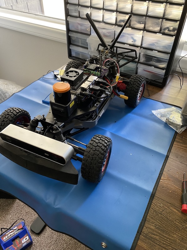
Here’s a picture of the finished build:
What’s next?
Now I need to get all of the electronic peripherals - the sensors, the motor controller, and the Jetson - setup properly. I’ll let you know how it goes.