Diff Drive Robot
Raspberry Pi, Arduino, and ROS robot
Abstract
I built a wheeled mobile robot, WMR, to complete the Coursera robotics specialization. In this project post, I will walk through how I built and tested it.
Introduction
Over the course of six weeks, I built this:
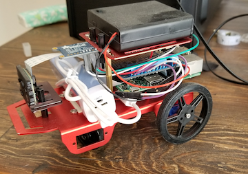
which did the following:
- Planned motion from a starting point to a goal point avoiding static obstacles
- Performed landmark recognition
- Estimated robot position within the map
- Controlled the robot to stably navigate
Before executing the above four tasks, I needed to get the materials and build the robot.
Building the Robot
The full list of build materials can be found here. The mechanical assembly followed very simply from the instructions provided with the chassis, wheels, etc… The electronic assembly was more complicated, so I will focus on these steps in this writeup.
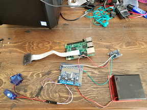
The main processing computer is a Raspberry Pi v3, into which a Raspberry Pi camera is directly plugged. The Pi, and therefore the camera, are powered by a 5V USB battery pack. Communication between the Pi and the low-level hardware, like motors and sensors, is achieved by soldering the male end of a 40-pin connector into an Arduino board.
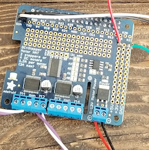
The Arduino board is also connected to a 5V power source which powers the board and the hardware peripherals connected to it.
Software
Operating System / OS
An Ubuntu distribution with ROS-Indigo was included with the project materials but, in order to use it, I had to flash the image onto an SD card and plug it into the Pi. After verifying successful installation of the OS, I was able to move on to the software that would control the robot.
Python / API
The ROS-Indigo distribution comes with an API that is accessible via Python. Rather than having to deal with C++, this API provides an easy way to code and test before implementation on the real robot.
Also included was a Python simulation that I used as a testbed before deploying code on the actual robot.
Calibration
Once the OS and ROS were installed, it was time to calibrate the robot. There were only two components that needed to be calibrated, but these steps were crucial.
The first system to calibrate was the motors, and this was accomplished by commanding a constant linear velocity over a fixed time and then measuring how far the robot travelled during this time. The specific speed and time used were 0.2 m/s and 1 sec, respectively. Depending upon whether the robot travelled too far or not far enough, the motor gains were tuned and the same experiment was reran until the measured distance travelled closely matched the desired 20cm. This step was necessary because, if I command the wheels to rotate at a certain rate, I want to know that they actually were going to!
The second system was the camera. As part of ROS, there is a camera calibration utility that uses OpenCV. After running a command from the command line, a GUI popped up that walked me through the process of moving a checkerboard near the camera so that the correct calibration parameters could be computed and stored on the robot. This step was necessary for both detecting landmarks and computing the camera’s distance to them.
Now that the robot was built and correctly calibrated, it was time to start designing and testing the code to get it to navigate autonomously.
Step 1: Construct a Plan
The first step is to build the high-level planner that will provide the robot with waypoints to drive through. The project specifically stated to use Dijkstra’s algorithm. This was not my first choice, but I wrote and tested it. I had seen in the earlier courses how it did, in fact, work; it was just terribly slow when compared to other planners. For the size of the map I was considering: ~1m x ~1m map broken into a grid of 20cm squares, execution speed was definitely not an issue.
Step 2: Landmark Recognition
The next step was to correctly configure the AprilTag detector ROS node. AprilTags are visual landmarks, like QR codes, that can be used as visual landmarks. When configured correctly, the camera will see one or more tags and the detector will construct a quaternion vector pointing towards the tag. From the quaternion, relative distance and orientation data, robot-to-tag, can be extracted and used to localize the robot within a map.
See here for a detailed outline of how AprilTags work in vision-based localization.
Step 3: Estimate Pose
To estimate the robot’s position and orientation within the mapped area, I used a linear Kalman filter that used velocity commands to propagate the state and uncertainty during the predict stage, and the tag detections during the update stage. The time from the IMU was used to process detections on a fixed clock-cycle. Besides the time, no other IMU output was used.
Step 4: Control
The final step was to build a controller that would stably navigate the robot through the set of waypoints computed in Step 1. I constructed a simple feedback controller that used the estimated state from Step 3 and a simple unicycle model for WMR. This led to a third-order state space model for the controller with three gains on the error states. Basic stability criteria for the gains was determined based upon an analysis of the eigenvalues of the closed loop system.
Merging this continuous controller with the grid-based path planner was simple: the center of each grid square from the optimal path was used as an intermediate waypoint for the robot to achieve. Each time the robot got close enough to its goal waypoint, that waypoint was popped from the plan’s list and the next waypoint became the new goal. Once all waypoints had been exhausted, meaning the robot was near the final goal, the robot would zero out the controls and stop.
Putting It All Together
Before bothering to test on hardware, I wanted to be sure that my algorithms would work. As I mentioned previously, part of the source distribution for the project included a little Python simulation that had all of the correct infrastructure calls to mask ROS protocol. Here is output from a sample run:

There were several nice things about simulation environment, specifically it
- had a simple yaml interface for adding and removing obstacles
- had a nice way of visualizing obstacles and tags
- plotted the robot’s estimated pose and its “true” pose against each other; this was important for tuning the Kalman filter
- plotted the trace of the trajectory so that the robot’s past path was visible
I will discuss what I didn’t like about the sim in the Concluding Remarks. All things considered, the sim was a good tool.
After getting good output from the simulation, I tested against a simple map where there were only three obstacles: the first three AprilTags. For the robot’s performance, please see this video. The robot navigates successfully to the desired goal point just to the right of the final tag and correctly stops.
Concluding Remarks
This was a really fun project to work on, and I am grateful that Coursera made this available. Hardware is usually difficult for me to work on in my side projects because my proficiencies are in software and algorithm design. Getting to dust off my soldering iron and build this robot, along with measuring and constructing the test course, was challenging but rewarding. Getting to see all of the elements culminating in the successful autonomous navigation of the robot was very gratifying. There were many challenges that were unseen along the way, but I think that they are important to mention here.
- Lighting effects: The Pi camera was crappy, like really crappy. It was only a few dollars, so I shouldn’t expect the world, but I had to carefully select test areas based upon lighting.
- Simulation and modeling assumptions: The simulation noise models were really unrealistic. Zeroing out the velocity commands from the controller resulted in the sim robot drifting forward at a slow, but appreciable, rate. Based on what I saw from the actual motors, this noise model was fundamentally incorrect. I would have preferred they not bother modelling the effects from noise if they weren’t going to accurately do so.
- Tag size: Based upon experimental observations, it appears that tag size does matter. With smaller tag sizes, I was able to get the robot to navigate much more precisely around and near tags. The tradeoff was that the landmarks were not detectable from as far. The AprilTags node from ROS allows for specifying tags of multiple sizes, so long as they have unique ID; e.g. only use one size for tag with id i.
For others considering trying this project or one similar to it, I highly recommend this web-based utility for viewing ROS telemetry; I found its indispensible.